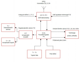
Multi-function PQ regulators for RES are designed in compliance with operational requirements of generating plants defined by energy law amendment # 211/2011 Sb. which substitudes the law # 458/2000 Sb. (Energy Law) et sequentia operational instructions published by distribution system operators (CEZ, E.ON, etc.).
Above mentioned requirements vary according to the source power and specific connection agreement. Basically it includes the system for limitation of active power performed in four steps: 0 per cent, 30 per cent, 60 per cent and 100 per cent. Step-by-step regulation of reactive power through required cos phi (0.95C – 0.97C – 1.00 – 0.97L – 0.95L) is usually required in case of bigger sources. In some case there is requiremnts for UQ regulation too.
PLC Regulators
PLC regulators are based on Siemens SIMATIC S7-1200 modular smart automatic machines. Regulator package usually includes CPU and digital IO modules, modul of PQ analogue measurement and HMI unit (and other optional items if needed).
| |
Input of required values: limitation of active power plus required cos phi is made by digital inputs. Issuing of control commands depend on particular technology of source and is made specific for each case. Usually is made by contact outputs.
Limitation of active power is usually provided by technology itself when the special interface (in expample Power Reducer Box for SMA inverters) implemented to the source. In such case PLC regulator is used to select required level of limitation and to memorizing this command. Rarely the limitation of active power can be done by disconnection of group of solar panels.
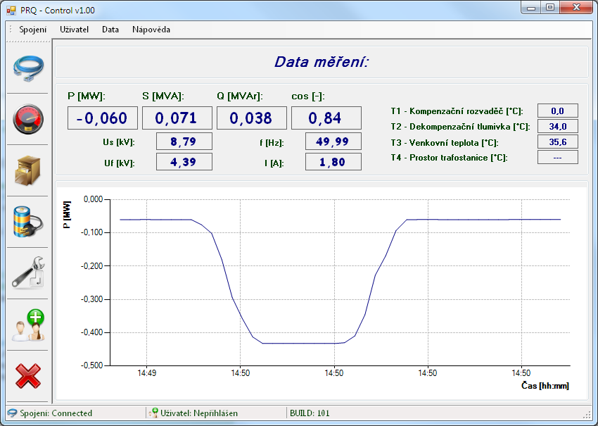
Regulation of reactive power is made by internal PID regulator with flexible time constants. Regulation deviation is set based on margin between measured and required value. PQ measurement derives from analog values of meauring converter itself. Alternativelly the measurements can be derived from pulse output of meter.
The direct setting of reactive power to the technology of plant is possible for bigger generating plants. The request is made as binary combination (seven capacity, seven induction and one neutral levels) by four digital outputs. Alternativelly it can be made by Modbus communication line. Compensation condensers and compensation coils make another regulation elements. Their switching is done as usual through power contactors. The regulator algorithm is set to minimize the switching numbers of each particular step and ensured their equal usage.
 |
 |
 |
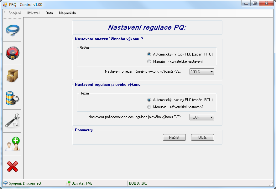 |
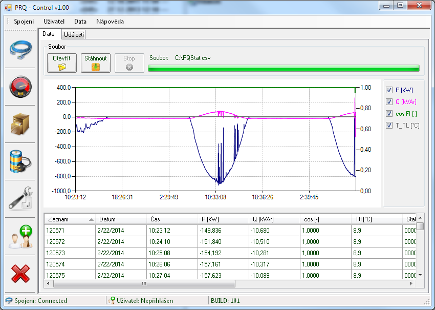
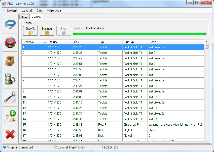
PLC regulator includes the log (limitation requests, alarms, etc.) and measured data registry enabling storage of data for about one month. Tthis way the system allows for diagnostics and backward checking.
PLC regulator can be connected to Local Area Network (LAN) of plant and allows even the access from internet after specific rules of routing are set.
MiReg
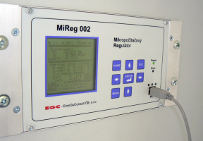
(no longer in standard production)Microcomputer regulator – MiReg is designed for regulation of reactive power of middle to large size RES connected to MV and HV. Its design originates from Terminal of Automated Functions for 110 kV/MV Transformer TAFT 112.
 |
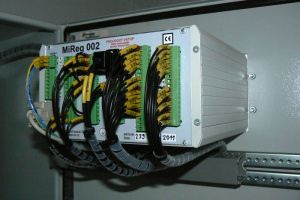 |
MiReg uses 24 digital inputs and 24 relay outputs. Moreover it contains single-phase analog measurement of voltage and current to PQ determination.
MiReg's basic task is maintaining defined value of power factor at point of connection. Required value is set by five galvanic-free inputs in steps: 0.95C – 0.97C – 1 – 0.97L – 0.95L.
Input values for regulation purpose are active and reactive power at point of connection which can be measured through counting of meter pulses or through sampling of AC current and voltage vawe. Pro of the first solution is that the measurement is identical with the one gained from certified meter. Its drawback is a low accuracy in case of very low power (in example during the consumption). It is also possible to combine both of these methods i.e. counting the pulses and switch to sampling in case of very low power.
Regulation of reactive power is made through:
- input of inverter phase angle in 15 steps using four binary contact outputs (zero power factor plus seven capacity steps and seven inductive steps)
- triggering of compensating and decompensating elements – coils and capacitors.
Regulation elements are split into groups with various priority and required power factor is always reached by the use of available elements with highest priority. The inverter regulation has usually the highest priority. If this is not enough capacitors are switched and as the last option coils are used. Each group performance and priority is set by application.
All regulations during operation are recorded in operation log in non-volatile memory. This log is accessible by appropriate application localy or remotely by i.e. GSM modem.
Due the out-of-date electronics and wide range of controlled technologies, MiReg is no longer in standard production and is fully replaced by PLC regulators.
